
Usb Otg Circuit Diagram
Step 1: What You Will Need -First thing you are going to need is a female standard USB connector and male USB micro B connector which you can get very cheap in your local electronic store. -You will also need very thin isolated copper wire. -Take your scissors and cut 4 pieces of wire the same length.
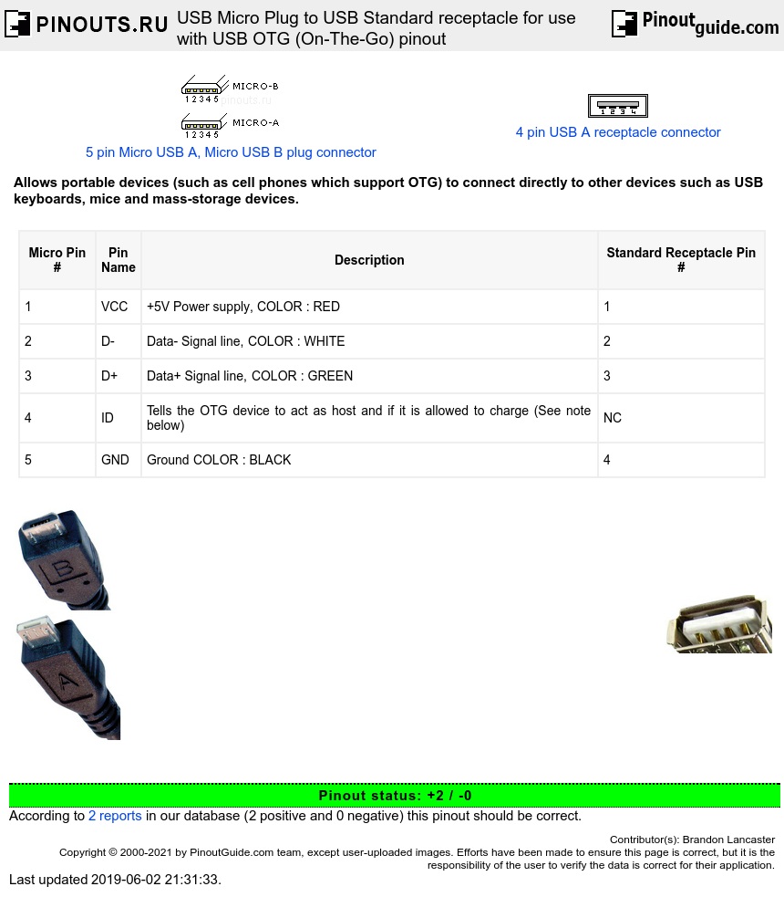
USB Micro Plug to USB Standard receptacle for use with USB OTG (OnTheGo) pinout diagram
1 Introduction The release of the On-The-Go (OTG) supplement to the USB 2.0 specification changed the USB world. For the first time, spec-compliant USB devices can talk to each other without requiring the services of a host computer.
Időben határozószó tál micro usb otg cable pinout óra Csökken kapzsi
All you need are two donor USB cables, one with a female type A end like you'd find on a USB extension cable (shown in the first photo here) and one with a male micro B end (second photo). When you're finished, you'll have a cable that plugs into your phone on one side and accepts a standard USB cable on the other.

Micro USB type B & OTG WIRING PINS to USB type A Diagrama de circuito, Esquemas electrónicos
You simply free your micro usb end from the rubber casing of the charge cable and then remove the metal housing by lifting two tabs. Once the tabs are lifted you can slide the housing away exposing the pins. After they are exposed you need to solder the pin next to the ground pin to the ground pin. The pinout is in the video.

Micro B Usb Wiring Diagram Microb Usb Vs Otg Wiring Diagram Micro Usb Otg Wiring Diagram USB
A Micro USB OTG (On-The-Go) cable is a special type of cable that allows you to connect peripherals, such as USB flash drives, keyboards, and game controllers, directly to your smartphone or tablet. It has a micro USB connector on one end and a standard USB connector on the other end. 2.

Usb Charger Wiring Diagram
This cable is most commonly used in mobile charger for charging mobile phones and as a USB data cable to connect mobile devices to tranfer files and images between personal computers and phones. Click here for the USB C 3.0 wiring diagram and charger cable internal wiring.

What is Micro USB OTG (OnTheGo)? Build DIY OTG Cable
Pinouts. Standard older micro USB connectors have five pins, while the less common 3.0 version has ten pins.. The fourth pin mode is what we call the USB on-the-go (OTG).. it's possible to use USB A to USB A cables to establish connections between a computer or USB device to another USB device with an A-style female port. So you can.
Micro Usb Cable Pinout Images and Photos finder
Step 1: What You Will Need You will need a Micro USB cable (in my case), a USB female port (took one off an old charger), a hobby knife, solder and hot glue and about 30 minutes of your time. Step 2: Cutting Into the USB Micro End and Making It a Host I used a cheap dollar store USB cord and I'm glad I did.

Usb Otg Cable Wiring Diagram Otg Cable Diy Android Charge Windows Best Of Wiring Diagram Micro
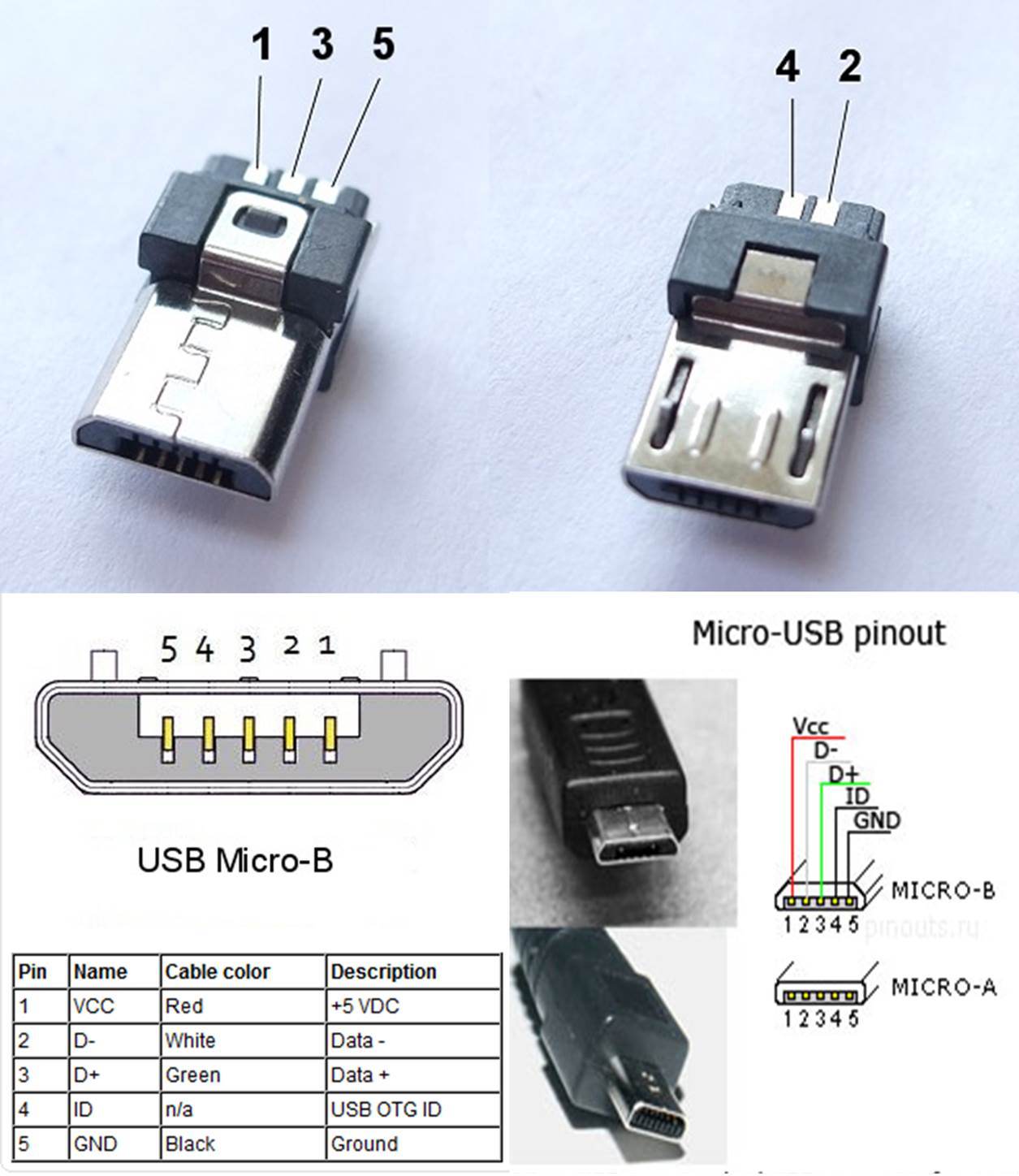
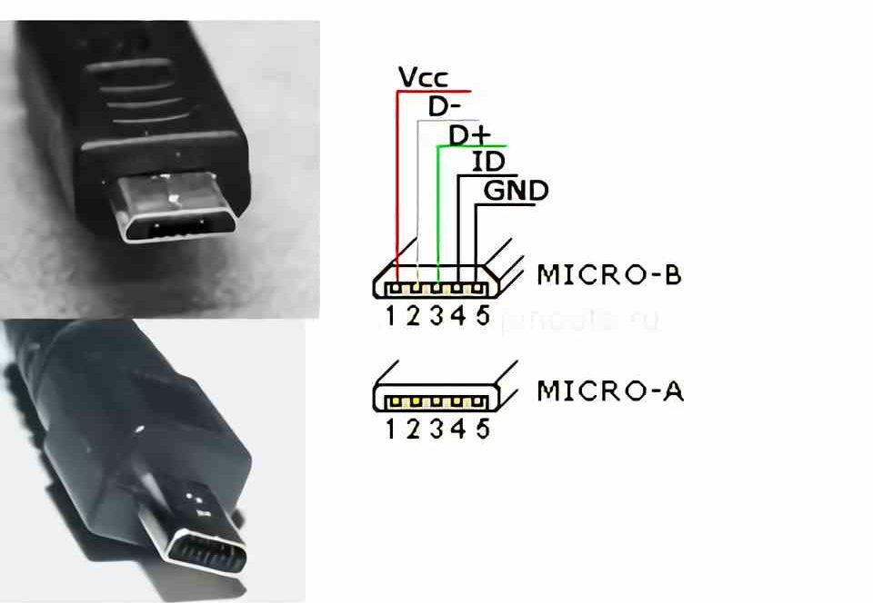
micro USB pinout signals USB is a serial bus. Micro-USB cable uses 4 shielded wires: two for power (+5v & GND), two for differential data signals (labelled as D+ and D- in pinout). NRZI (Non Return to Zero Invert) encoding scheme used to send data with a sync field to synchronise the host and receiver clocks.
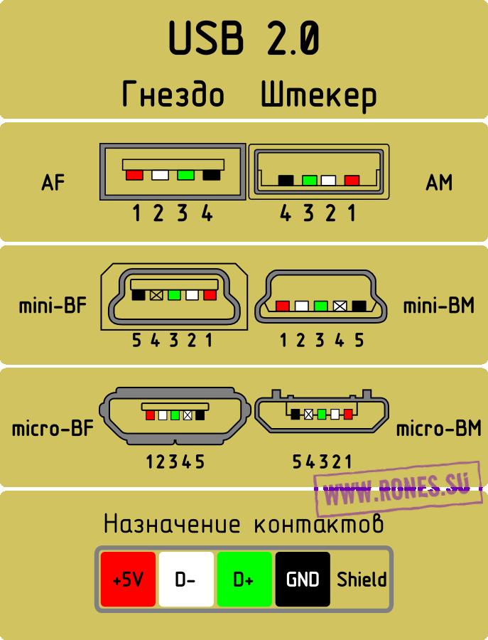
Розпіновка роз'ємів USB 2.0 SPUTNIKUA Супутникове телебачення, T2, SMART TV, Черкаси
Micro USB Pinout. The USB Micro is thinner and has a higher data transfer rate than the USB Mini. It's typically used to charge small electronics and comes in two varieties: Micro A is rectangular, whereas Type Micro B is camper-shaped. The USB Micro also has 5 pins similar to that of the USB Mini, where the additional pin supports OTG.
Typy USB konektorů A, B, C, MicroUSB a MiniUSB ITIGIC
Cut a piece of standard USB cable that is about 3 inches long. 2. Strip away the outer insulation from both ends of the cable, exposing the inner wires. 3. On one end of the cable, twist the wire strands together to create a solid connection. 4. solder the wire to the micro USB connector.

MICRO USB OTG CABLE
USB On-The-Go ( USB OTG or just OTG) is a specification first used in late 2001 that allows USB devices, such as tablets or smartphones, to also act as a host, allowing other USB devices, such as USB flash drives, digital cameras, mouse or keyboards, to be attached to them.
Micro Usb Pin Diagram
Introduction. USB On-the-Go (OTG) allows two USB devices to talk to each other without requiring the services of a personal computer (PC). Although OTG appears to add peer-to-peer connections to the USB world, it does not. Instead, USB OTG retains the standard USB host/peripheral model, in which a single host talks to USB peripherals.

Anime Sketch Wallpaper Hd uit [50+] Diy Rca To Usb Wiring Diagram, Usb Wire Diagram Schematic
A USB connector is the socket, port, or jack into which the plug end of a USB cable or USB-powered device is inserted. USB connectors are typically female, while the USB plug on the cable is male. Rectangular, slot-shaped USB type-A connectors are most common and can be found on computers, personal electronics, and peripherals.

Pix For > Micro Usb Otg Pinout Зарядка, Электронная схема, Штекеры
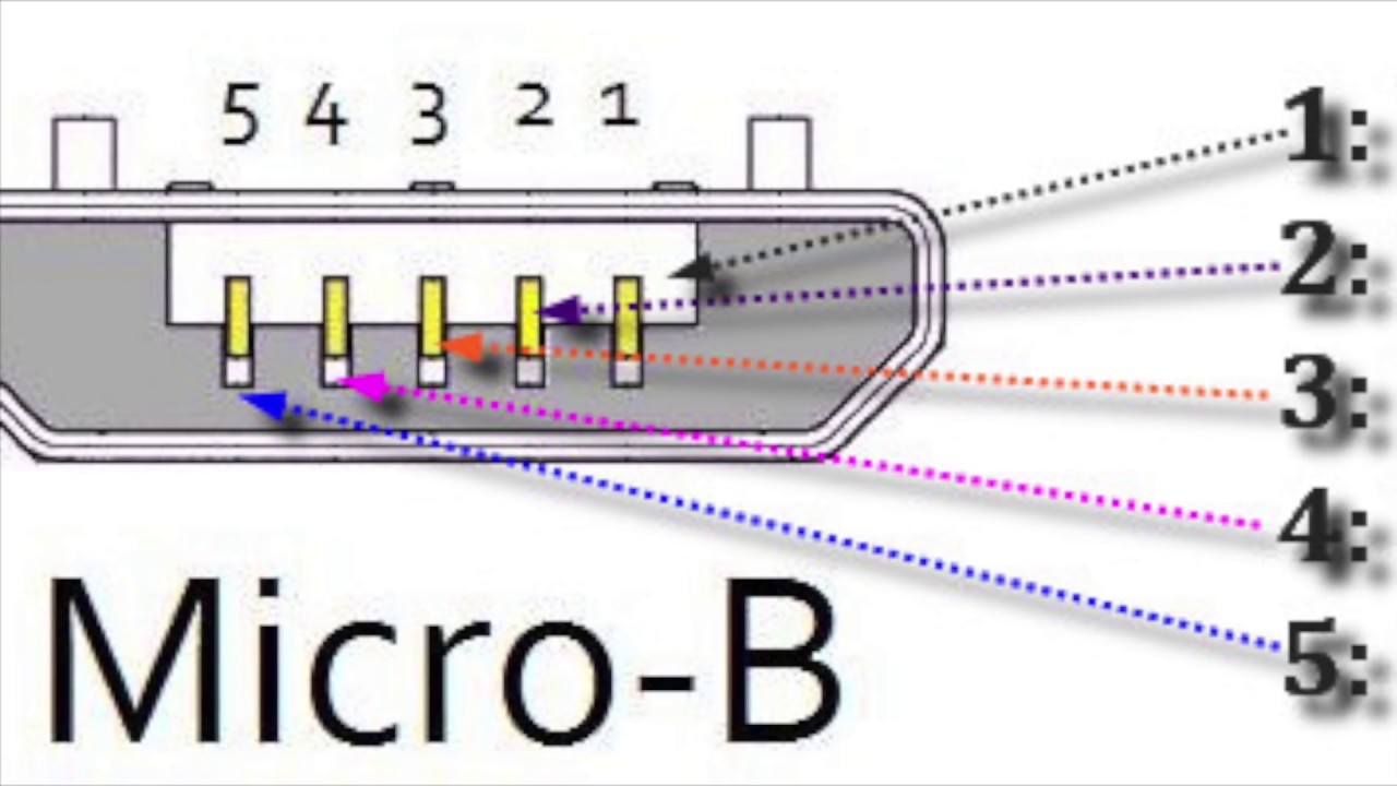
Micro USB Pinout Diagrams Looking at the micro connector on a cable, all generations have pins numbered 1-4, ascending, from left to right on the main trapezoid. Third generation connectors have pins 6-10, ascending, from left to right, on the added side rectangle.
USB OTG mit Ladefunktion
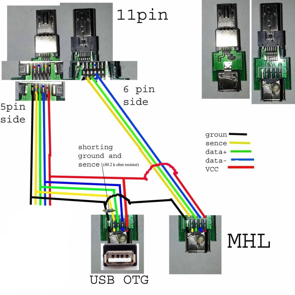
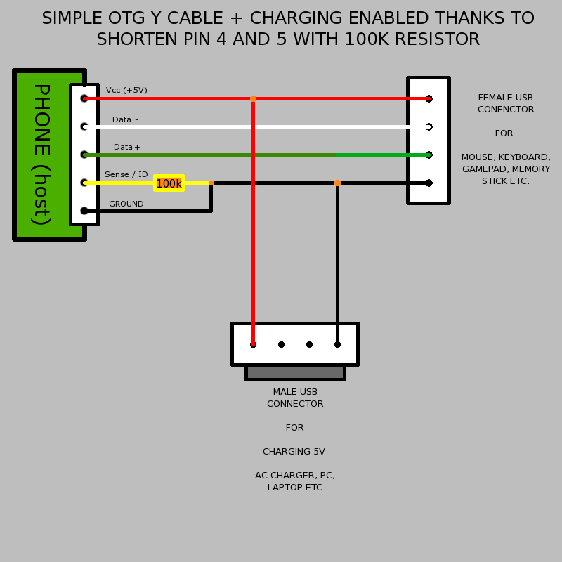
Allows portable devices (such as cell phones which support OTG) to connect directly to other devices such as USB keyboards, mice and mass-storage devices. Note-The ID pin can be directly connected to ground. This will tell the OTG device that it can not charge (and hence must supply current to VCC) but should act as a USB host.